
TECHNICAL GUIDE
Channel Letter Mounting Guide for Factory and Installer Coordination
Compare direct, raceway, backer-panel, rail and stand-off mounting inputs before the production drawing is approved.
- Mounting surface and access review
- Stud, rail, raceway and cable-exit planning
- Templates and labeled installer hardware
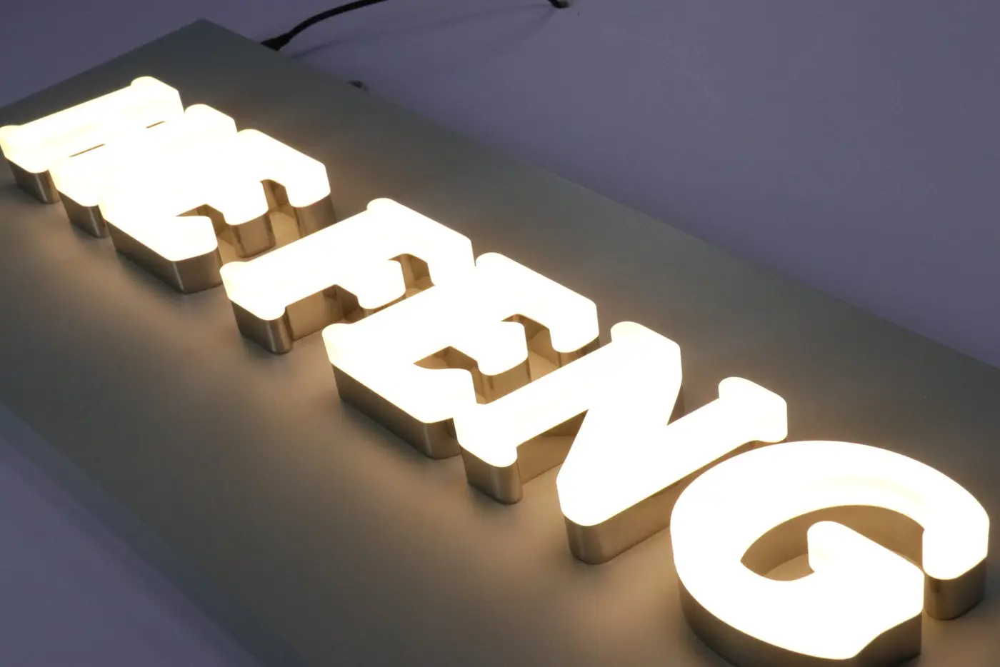
1. Direct Stud Mounting
Individual letters mount directly to the wall using studs or threaded fixings. The drawing should define stud positions, wall access, cable exits and template format.
- Confirm wall material and drilling restrictions
- Define stud length and stand-off distance
- Coordinate cable exits behind each letter
- Use an approved placement or drilling template
2. Raceway Mounting
Letters are assembled on a fabricated raceway that contains wiring and power supplies. Raceway size, color, access covers and wall fixings must be coordinated with the fascia.
- Confirm raceway depth and maximum width
- Match or specify raceway finish
- Provide driver and wiring access
- Define local wall fasteners and cable entry
3. Backer Panels and Rails
Backers or rails can group letters, cover previous fixing areas or provide a controlled interface on difficult façades.
- Define visible panel shape and finish
- Review wind exposure and structural support
- Coordinate removable covers and access
- Identify divided sections for shipment
4. Halo-Lit Stand-Offs
Halo-lit letters require a controlled distance from the wall so light can reflect evenly. Wall color, texture and cable concealment affect the result.
- Confirm stand-off distance
- Review wall reflectance and texture
- Position cable exits behind letter bodies
- Provide driver access outside visible areas
5. Installer Handover
Letters, rails, raceways, templates and hardware should use the same drawing and project codes.
- Letter and carton labels
- Mounting template or hole pattern
- Hardware list and grouped bags
- Wiring and driver references
DECISION REFERENCE
Compare Common Channel Letter Mounting Interfaces
The mounting method changes wall penetrations, wire routing, service access and what the local installer needs from the factory.
| Mounting interface | Typical coordination benefit | Confirm before fabrication |
|---|---|---|
| Direct stud mounting | Keeps letters visually separate and can minimize visible support hardware. | Wall structure, stud pattern, drilling template, cable exits and rear access. |
| Raceway mounting | Consolidates letters and wiring on a serviceable carrier. | Raceway size and finish, fixing points, power entry, access cover and local limits. |
| Backer panel or rail | Provides a controlled support plane where the fascia needs load distribution. | Panel or rail dimensions, structural fixing points, finish and drainage. |
| Halo-lit stand-offs | Creates the designed separation for reflected light. | Stand-off depth, wall color and texture, wire concealment and cleaning access. |
BUYER AND PROJECT CHECKLIST
Confirm the Site Interface and Installer Handover
Treat the wall and the sign as one interface. A visually correct letter set can still create site problems when the structure, access or cable path is unresolved.
- Record wall or fascia construction and any concealed structure.
- Confirm allowable penetrations, landlord criteria and weather exposure.
- Show mounting centers, templates, stand-offs and cable exits on approved drawings.
- Identify power entry and the access needed for drivers or raceway covers.
- Confirm which anchors, sealants and field electrical parts the installer will supply.
Review the interface with the channel letter product, resolve it during engineering and drawing review, and include retail fascia or landlord constraints for retail and shopping-center projects.
RELATED TECHNICAL GUIDES
Related Technical Guides
Use these guides to connect lighting intent, mounting format and electrical access.
Front-Lit vs Halo-Lit Channel Letters
Relate the lighting effect to backs, stand-offs and wall reflection.
Relevant context: face light, halo light and wall conditions
Raceway vs Flush-Mount Channel Letters
Compare service access and wall penetrations for two common approaches.
Relevant context: raceway, direct mount and installer preference
LED Sign Voltage & Power Planning
Coordinate driver position and cable exits with the mounting plan.
Relevant context: electrical access and field connection
TECHNICAL FAQ
Channel Letter Mounting Questions
Use these answers to identify open project inputs before quotation or drawing approval.
Who selects the final anchors?
The local installer or responsible project professional should select anchors for the verified wall construction and applicable requirements. Factory drawings can show intended fixing locations and interfaces.
Can a mounting method change after drawings are approved?
It can, but the change may affect backs, studs, raceway size, cable exits, templates and packing. Revise and approve the affected drawing details before fabrication continues.
Do halo-lit letters need a specific stand-off depth?
The required depth depends on the desired halo, wall color and texture, letter size and LED layout. Confirm the project-specific stand-off on the drawing.
What should the installer receive?
Provide approved elevations, mounting templates or patterns, labeled hardware, electrical notes and a clear list of items that must be sourced locally.
START YOUR PROJECT
Apply This Guide to Your Project
Upload your current artwork and site notes. We will identify which guide inputs are already complete and which still need confirmation.